-
- Product Application Introduction
1.1 Application Scenario Introduction
1.1.1 Grid-connected AC coupling applications

Figure 1-1 Schematic diagram of grid-connected AC coupling access
Grid-tied AC coupling applications are suitable for the following situations:
- The customer already has a photovoltaic system (PV + photovoltaic grid-connected inverter);
- Customers need storage for power backup, peak load shifting, photovoltaic consumption, or demand regulation;
- The system is not allowed to operate off-grid, and the system is required to have anti-islanding and anti-backflow functions.
At this time, the AC side of the energy storage system is connected to the grid-connected distribution cabinet, and then connected to the power grid through the grid-connected distribution cabinet.
1.1.2 Grid-connected DC coupling applications

Figure 1-2 Schematic diagram of grid-connected DC coupling access
Grid-connected DC coupling applications are suitable for the following situations:
- The customer has not configured PV yet, but wants to configure a PV storage system;
- Customers need storage for dynamic capacity expansion, photovoltaic arbitrage, peak load shifting, or demand regulation;
- The system is not allowed to operate off-grid, and the system is required to have anti-islanding and anti-backflow functions.
At this time, the photovoltaic power is directly connected to the DCDC to charge the energy storage system. The AC side of the energy storage system is connected to the grid-connected distribution cabinet, and then connected to the grid through the grid-connected distribution cabinet.
1.1.3 On-grid and off-grid DC coupling applications

Figure 1-3-1 Schematic diagram of the on-grid and off-grid DC coupling scheme 1

Figure 1-3-2 Schematic diagram of the second access scheme for on-grid and off-grid DC coupling
On-grid and off-grid DC coupling applications are suitable for the following situations:
- The customer has not configured PV yet, but wants to configure a PV storage system;
- Customers need storage for dynamic capacity expansion, peak load shifting, demand regulation when connected to the grid, or for photovoltaic arbitrage and backup power when off-grid;
- The load must not be powered off and must be supported and off-grid.
At this time, the energy storage system needs to be connected to STS. When connected to the grid, it is the same as 1.1.3. When it is detected to be off-grid, STS needs to perform seamless switching, the photovoltaic power is stored in the energy storage system, and the energy storage system discharges to the load. When off-grid, the diesel engine can also be connected as another backup energy source.
1.2 Application environment requirements
The normal working environment of the system should meet the following requirements:
- Working environment temperature: -20℃~50℃.
- Relative humidity ≤90%RH, no condensation on live parts.
- Altitude ≤ 2000m, when exceeding the altitude, the system needs to be derated.
- The air should not contain dust and conductive, corrosive, or explosive particles and gases that may affect normal work;
- No vibration or shock, vertical inclination ≤5°.
- Other areas with extreme temperatures (such as extreme cold or extreme heat) and marine climates (such as islands) are not within the scope of use of this product.
2 Product Features
This product has the following features:
- High integration: The integrated cabinet can simultaneously integrate multiple devices such as battery system, battery management system (BMS), energy management system (EMS), power control system (PCS), DC-DC converter (DC/DC) and static transfer switch (STS), to maximize the system integration.
- Flexible configuration: Users can choose appropriate device configuration according to different usage scenarios, and one product can meet the needs of multiple application scenarios.
- Intelligent application: The energy management system (EMS) can optimize the mode configuration according to the specific usage scenario, provide customers with the best usage plan, and maximize customer benefits.
- Safe and reliable: The system is integrated with first-line brand components. All components and systems have undergone strict safety certification and have multiple protection measures for battery management system (BMS) software and hardware. In addition, the cloud platform operation and maintenance system provides customers with comprehensive operation and maintenance support to ensure the safe and stable operation of the system, thereby solving customers’ worries.
- 3.2.1 System parameter table
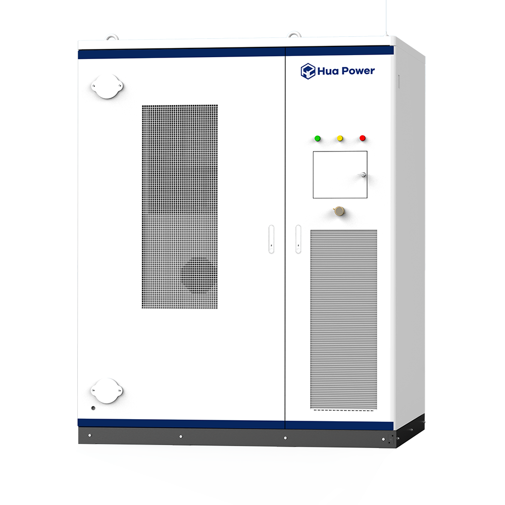
Figure 3-2 System diagram
Table 3-1 Basic system parameters
Item Parameter Type Parameters 60kW / 120kWh 1 Battery side parameters Cell Type LFP 3.2V / 280Ah 2 System battery configuration 1P 9S 3 System capacity configuration 129.024kWh 4 Battery voltage range 388.8 ~ 518.4 V 5 Discharge Depth 90%DOD 6 Maximum charge and discharge current on DC side 180A 7 Maximum charging and discharging power on DC side 60kW 8 AC side parameters (Grid-connected)
AC output power 66kVA@45℃ 9 Maximum AC current 100A 10 Rated grid voltage 400V/230V (-20%~15%) 11 Nominal grid frequency range 50Hz/45Hz~52Hz, 60Hz/55Hz~62Hz 12 Harmonic distortion <3% (at rated power) 13 Power Factor -1~1 lead or lag 14 AC side parameters (Off-grid)
Rated output voltage 400V/230V (-5%~5%) 15 Harmonic distortion <2%(under resistive load) 16 Unbalanced three-phase load 100% 17 Rated frequency 50Hz/45Hz~55Hz, 60Hz/55Hz~65Hz 18 Maximum AC power 66kVA 19 Photovoltaic input parameters Photovoltaic voltage range 200~850V 20 MPPT voltage range 350~800V 21 MPPT input quantity 4- way 22 Maximum photovoltaic input power 32A *4 /19.2kW *4 23 General parameters Efficiency Battery side: ≥90% Hybrid Inverter maximum efficiency: 98% 24 External communication interface Ethernet 25 Temperature control method Air-cooling 26 Dimensions (W*D*H) 1200* 900 *1800mm 27 Weight <1.5t 28 Protection level IP54 29 Corrosion resistance C3 30 Operating temperature range -20℃~ 45 ℃ (>40℃ derating) 31 Operating humidity range 5%~95%RH, non-condensing 32 Altitude 3000 meters (>3000 meters, derating) 33 noise ≤75dB 34 Certification Battery: CB, UN38.3 35 Hybrid Inverter Certification: EN50549, IEC62477, IEC6100, IEC62109
System: CE, UN3536
60kW 129kWh Solar Energy Storage System All-in-one BESS Lithium Battery Cabinet EVE 314Ah 280Ah